Descripción del Producto
DIN 8187 Industry Sprocket Made to Order Stainless Steel Sprocket for Roller Chain & Agriculture Chain & Food Machinery (DIN, ANSI Standard)(06B20T)
Descripción del Producto
1. Produce strictly in accordance with ANSI or DIN standard dimension
2. Material: C45 steel / Stainless Steel 304 & 316
3. Standard: ANSI, DIN, JINS, ISO, Standard America or customer drawing
4. Pilot bore, finished bore, taper bore and special bore.
5. Bright surface and high precision
6. Advanced heat treatment and surface treatment craft
7. Best quality and competitive price.
8. Welcome OEM / ODM
9. Application: Sprocket is mainly used in agricultural machinery, conveying machinery, mine mining machinery, construction machinery, mechanical transmission equipment of oil and so on.
10. Processing equipment: Hobbing machine, Slotting machine, CNC lathes and other equipment.
11. Sprocket models: Contains special sprocket (custom) according to customer’s drawings, standard sprocket (American standard and metric).
Features:Sprocket / Gear / CZPT / Steel CZPT / Lost wax casting and accessories / Investment casting
Materials: Carbon steel, alloy steel, stainless steel, ductile iron, gray iron, high chromium iron
| Product name | DIN 8187 Industry Sprocket (06B20T) |
| Materials Available | 1. Stainless Steel: SS304, SS316, etc |
| 2. Alloy Steel: C45, 45Mn, 42CrMo, 20CrMo, etc | |
| 3. OEM according to your request | |
| Tratamiento de superficies | Heat treatment, Quenching treatment, High frequency normalizing treatment, Polishing, Electrophoresis paint processing, Anodic oxidation treatment, etc |
| Characteristic | Fire resistant, Oil resistant, Heat resistant, CZPT resistance, Oxidative resistance, Corrosion resistance, etc |
| Design criterion | ISO DIN ANSI & Customer’s Drawing |
| Size | Customer’s Drawing & ISO standard |
| Application | Industrial transmission equipment |
| Package | Wooden Case / Container and pallet, or made-to-order |
| Certificate | ISO9001: 2008 |
| Advantage | Quality first, Service first, Competitive price, Fast delivery |
| Delivery Time | 20 days for samples. 45 days for official order. |
Fotos detalladas
View more products,please click here…
Company Profile
| Estándar o no estándar: | Estándar |
|---|---|
| Solicitud: | Industry |
| Dureza: | Superficie del diente endurecida |
| Material: | Alloy Steel/Stainless Steel |
| Tipo: | Rueda de espigas |
| Sample: | for Free |
| Muestras: |
US$ 0/Piece
1 unidad (pedido mínimo) | |
|---|
| Personalización: |
Disponible
| Solicitud personalizada |
|---|
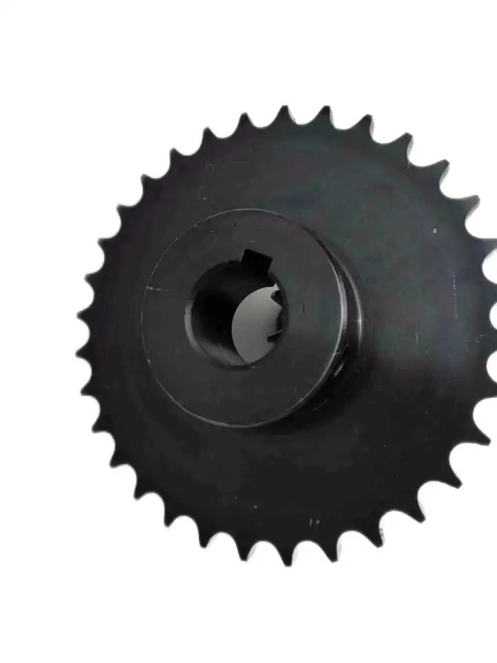
Cálculo de los requisitos de par para un conjunto de piñón de rueda
El cálculo del par motor necesario para un conjunto de piñón y rueda implica considerar diversos factores que influyen en la carga de par. Este par es crucial para seleccionar el motor o la fuente de alimentación adecuados para accionar el sistema eficazmente. A continuación, se presenta una guía paso a paso:
- 1. Determinar el par de carga: Identifique el par necesario para vencer la resistencia o carga del sistema. Esto incluye el par necesario para mover la carga, vencer la fricción y acelerarla, si corresponde.
- 2. Identifique el radio de la rueda dentada: Mida el radio del piñón (distancia desde el centro del piñón hasta el punto de contacto con la cadena o la correa).
- 3. Calcula la tensión en la cadena o correa: Si se utiliza una transmisión por cadena o correa, calcule la tensión de la cadena o correa. La tensión afecta al par motor necesario para la transmisión de potencia.
- 4. Contabilizar las pérdidas de eficiencia: Considere la eficiencia del sistema. No toda la potencia de entrada se convertirá en potencia de salida debido a la fricción y otras pérdidas. Tenga en cuenta esta eficiencia en sus cálculos.
- 5. Utilice la ecuación del torque: El par motor (T) se puede calcular utilizando la siguiente ecuación:
T = (Par de carga × Radio de la rueda dentada) ÷ (Eficiencia × Tensión)
Es fundamental utilizar unidades de medida consistentes (por ejemplo, newton-metros o pies-libras) para todos los valores de la ecuación.
Recuerde que las condiciones del mundo real pueden variar, y es recomendable añadir un factor de seguridad a los requisitos de par calculados para garantizar que el sistema pueda soportar cargas máximas inesperadas o variaciones en las condiciones de funcionamiento.
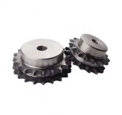
Inspecting a wheel sprocket for Wear and Tear
Regular inspection of the wheel sprocket is essential to ensure their proper functioning and to identify any signs of wear and tear. Here are the steps to inspect a wheel sprocket:
- Visual Inspection: Start by visually examining the wheel sprocket for any visible signs of wear, damage, or deformation. Look for cracks, chips, dents, or any irregularities on the surface of both components.
- Check for Misalignment: Verify that the wheel sprocket are properly aligned with each other. Misalignment can lead to accelerated wear and affect the overall performance of the system.
- Measure Wear: Use calipers or a wear gauge to measure the sprocket’s tooth profile and the wheel’s rolling surface. Compare these measurements with the original specifications to determine if significant wear has occurred.
- Inspect Teeth and Chain Engagement: If the wheel sprocket are part of a chain drive system, closely examine the sprocket teeth and chain engagement. Worn or elongated teeth can cause poor chain engagement and lead to premature failure.
- Lubricación: Check the lubrication of the wheel sprocket. Insufficient or excessive lubrication can cause increased friction, leading to wear and reduced efficiency.
- Bearing Condition: If the wheel is mounted on a shaft with bearings, inspect the bearings for any signs of wear, noise, or rough movement. Properly functioning bearings are crucial for the smooth operation of the system.
- Inspect Mounting Hardware: Ensure that all nuts, bolts, and other mounting hardware are securely tightened. Loose fasteners can cause vibration and misalignment issues.
- Check for Contaminants: Remove any debris, dirt, or foreign particles that may have accumulated on the wheel or sprocket. Contaminants can accelerate wear and damage the components.
- Replacement or Maintenance: Based on the inspection results, determine if any parts need replacement or if maintenance is required. Address any issues promptly to prevent further damage and maintain the system’s performance.
Regularly scheduled inspections and maintenance can help prolong the lifespan of the wheel sprocket assembly, optimize performance, and ensure the safety of the mechanical system.
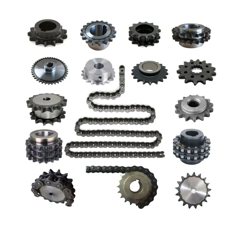
Calculating Gear Ratio for a wheel sprocket Setup
In a wheel sprocket system, the gear ratio represents the relationship between the number of teeth on the sprocket and the number of teeth on the wheel. The gear ratio determines the speed and torque relationship between the two components. To calculate the gear ratio, use the following formula:
Gear Ratio = Number of Teeth on Sprocket ÷ Number of Teeth on Wheel
For example, if the sprocket has 20 teeth and the wheel has 60 teeth, the gear ratio would be:
Gear Ratio = 20 ÷ 60 = 1/3
The gear ratio can also be expressed as a decimal or percentage. In the above example, the gear ratio can be expressed as 0.3333 or 33.33%.
It’s important to note that the gear ratio affects the rotational speed and torque of the wheel sprocket. A gear ratio greater than 1 indicates that the sprocket’s speed is higher than the wheel’s speed, resulting in increased rotational speed and reduced torque at the wheel. Conversely, a gear ratio less than 1 indicates that the sprocket’s speed is lower than the wheel’s speed, resulting in decreased rotational speed and increased torque at the wheel.
The gear ratio is crucial in various applications where precise control of speed and torque is required, such as bicycles, automobiles, and industrial machinery.


editor by CX 2023-07-27